Wiring in accessories is not necessarily difficult. However, it can become confusing, time consuming, and open up the possibility for problems if not done correctly. Although 12V systems are fairly safe you should consult a professional before attempting wiring yourself.

We'll break this down into four parts:
1) Devices
2) Switches
3) Relays
4) Easy Alternative (Nearly Fool Proof)
Important:
*Always figure out the amp draw of whatever device you will be using for each circuit. This is important so that you can select the correct wire gauge and fuse rating. ALWAYS fuse incoming power wires.*
We'll break things down in this article to try to make things as easy as possible.

1) Devices:

Wiring on the device side is fairly simple. Most accessories only require power (12V+) and Ground (-). The red wire is generally your power wire, and black is generally the ground. You should always verify which wire is which by referring to the instruction manual before wiring them in.
*Some modern lights now have backlighting which is generally represented with a blue wire. We usually like to wire this to ignition which is easily pulled from the fuse box or a running light on the vehicle.

2) Switches:
2-pin rocker switch diagram:

Two pin switches are the easiest to understand and wire. You simply run power through the switch in order to control the electricity flow. The downside to these switches is that they usually are not lighted.
3-pin rocker switch diagram:

5-pin rocker switch diagram:

There are a number of different switches that can be used to wire in an accessory but generally most people use rocker switches. There are variations of these switches bust for most cases people use 5 or 6 pin rocker switches. 5-pin switches are what's called a "single throw" switch. 6 pin have a couple variation options but are generally a On / Off / Momentary On.
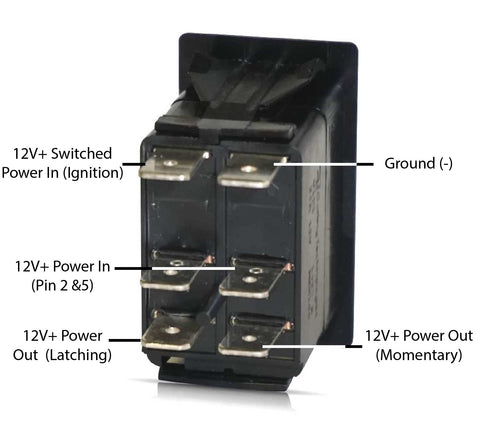
6-pin rocker switch diagram:

The 6 pin rocker switches offer a latching element as well as a momentary side. These are commonly used for engine starters. Wiring is a bit different on these but essentially the same concept.
8-pin rocker switch diagram:

The 8 pin rocker switches. Most people will not use or need them. However, if you are wiring in a winch this would be the switch for you. These switches offer momentary switching both up and down. Meaning for the switch to be "in use" someone will have to push it either up or down and hold it.
3) Relays
A relay is simply an electronic switch that operates using an electrical coil. These are typically used in order to reduce the amount of power that will be running through a switch. By using a relay you can run the power through it instead of the switch, and instead use the switch to simply turn on the relay. You could also use your vehicle ignition (accessory) input from your key to turn on different devices such as a fuel pump, running lights, etc...
4 Pin Relays:

5 Pin Relays:

Above is an example of the most common relay you will find on the market. Most relays use the same pin number / power routing but always check with the manufacturer prior to installing their relay.
4) PWR-LINK™ The Easy Way
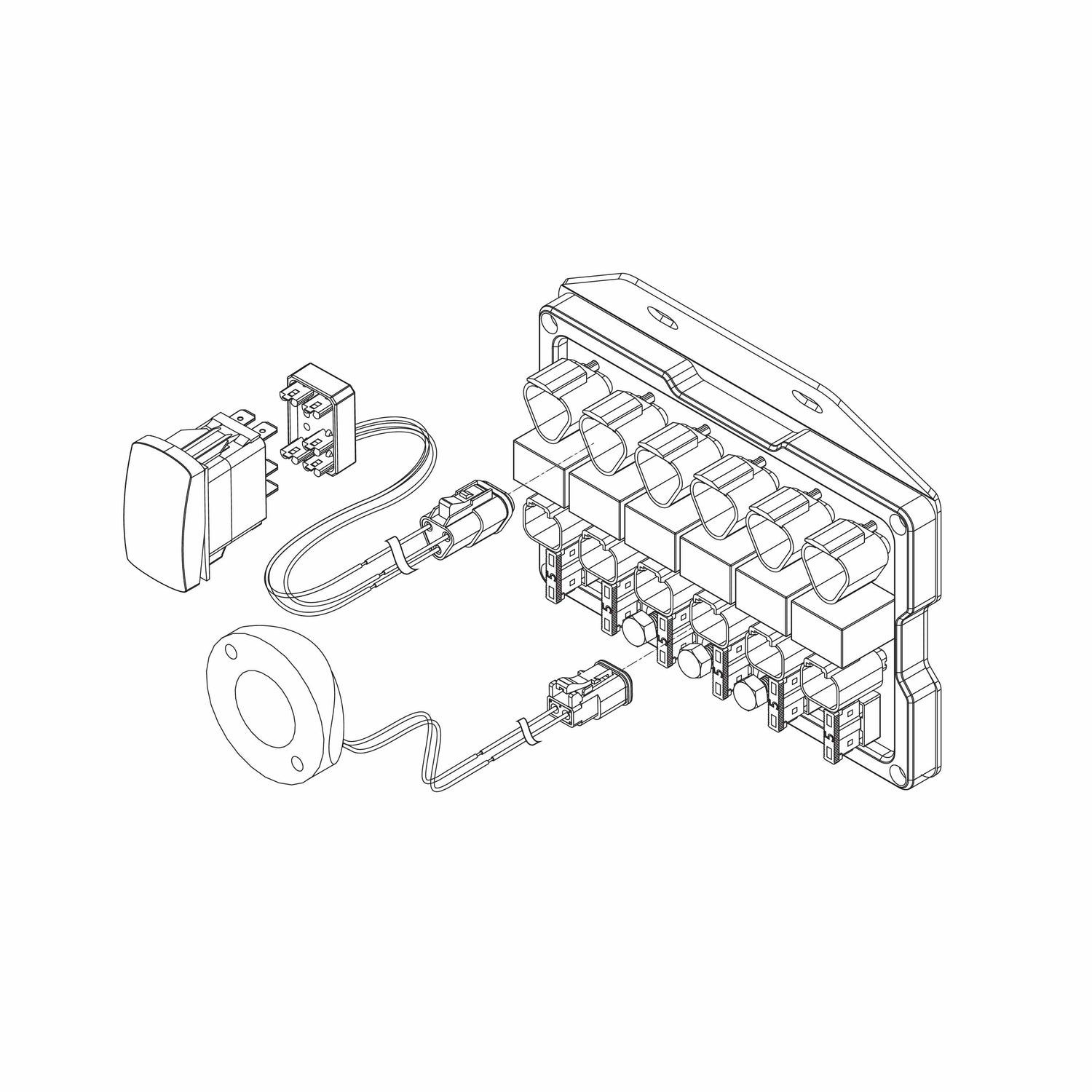
We understand the difficulties of wiring and installing accessories onto a vehicle. Keeping the wires neat and your connections secure also presents a challenge for many installers. This is why we designed and patented the PWR-LINK™ power distribution system.

The PWR-LINK™ is easily fused, relays are built in, and keyed waterproof connectors are provided for secure electrical connections. The kit includes labels to identify each circuit and keep things neat and organized.
We also developed the Switch-Blade which makes wiring a rocker switch a plug-n-play affair.

For more information and pricing check out our PWR-LINK™ here.


Leave a comment
All comments are moderated before being published.
This site is protected by hCaptcha and the hCaptcha Privacy Policy and Terms of Service apply.